🎥 Watch this quick video explanation before reading the detailed guide.
Introduction to Rectifiers: Converting AC to DC
In the world of electronics, power is the lifeblood of every device. However, there is a fundamental challenge: the electricity supplied by our wall outlets is Alternating Current (AC), while almost all modern electronic gadgets—like your smartphone, laptop, and LED lights—require Direct Current (DC) to function. This is where the rectifier comes into play.
A rectifier is an electrical device that converts alternating current, which periodically reverses direction, to direct current, which flows in only one direction. This process is known as rectification. Rectifiers are essential components in power supplies, allowing electronic devices to operate safely and efficiently on DC power.
Why Do We Need Rectification?
AC is excellent for transmission, but electronics need stable DC power to function safely and correctly.
To understand why rectifiers are so important, we must look at how AC and DC differ. AC is excellent for transporting electricity over long distances because it can be easily stepped up or down using transformers. However, the internal components of electronics (like transistors and integrated circuits) need a constant, steady voltage to maintain their logical states and power their internal processes. Without a rectifier, the reversing polarity of AC would damage these sensitive components.
Types of Rectifiers
There are mainly two types of rectifiers used in power electronic circuits:
- Half-Wave Rectifier: The simplest form of a rectifier that uses only one half of the AC cycle.
- Full-Wave Rectifier: A more efficient rectifier that utilizes both the positive and negative halves of the AC cycle.
The Half-Wave Rectifier: Construction and Working
The Half-Wave Rectifier is the most basic circuit used to convert AC to DC. It is primarily used in low-power applications where efficiency is not the top priority.
Construction of a Half-Wave Rectifier
- Step-Down Transformer: A step-down transformer is used to reduce the high AC voltage (usually 230V or 110V from the mains) to a lower AC voltage suitable for the diode.
- Single Diode: A single semiconductor diode is the heart of the circuit. It acts as a one-way valve for electricity.
- Load Resistor (RL): A resistor is connected to the circuit to control and utilize the DC output. This represents the device you are trying to power.
[Image of half wave rectifier circuit diagram]
Working Principle of Half-Wave Rectifier
When the AC voltage is supplied to the primary of the transformer, it induces a secondary voltage. This AC voltage consists of two cycles: positive and negative.
1. During the Positive Half-Cycle
During the positive half-cycle, the top terminal of the transformer becomes positive relative to the bottom. In this state, the diode becomes forward biased. Because it is forward biased, it allows current to pass through it. The current flows through the diode and reaches the load resistor, resulting in a positive DC voltage output.
2. During the Negative Half-Cycle
During the negative half-cycle, the AC voltage reverses its polarity. The top terminal becomes negative. Now, the diode becomes reverse biased. In reverse bias, a diode acts as an insulator and blocks the current. Since the current is blocked, no voltage reaches the load, and the output is zero during this phase.
Output Characteristics
The final output of a half-wave rectifier consists of pulses of DC voltage. It is not a smooth, flat line like a battery. Instead, it is pulsating DC. Because it loses 50% of the input power (the negative cycle), it is considered inefficient for high-power needs and often requires additional filtering (like capacitors) to create a steady DC supply.
The Full-Wave Rectifier: Enhanced Efficiency
To overcome the limitations of the half-wave rectifier, engineers use the Full-Wave Rectifier. This circuit ensures that current flows to the load during both halves of the AC cycle.
Construction of a Full-Wave Rectifier
- Center-Tap Transformer: This special transformer has an extra wire connected to the exact middle of the secondary winding. It provides two equal and opposite AC voltages.
- Two Diodes: Unlike the half-wave version, two diodes are used to conduct current during alternate half-cycles.
- Load Resistor: Connected between the center tap and the junction of the two diodes.
[Image of center tap full wave rectifier circuit diagram]
How a Full-Wave Rectifier Works
1. The Positive Half-Cycle
During the positive half-cycle of the input AC, the first diode (D1) becomes forward biased while the second diode (D2) remains reverse biased (off). Current flows through D1 and the load, producing an output.
2. The Negative Half-Cycle
During the negative half-cycle, the AC voltage reverses. Now, D1 becomes reverse biased and turns off, but D2 becomes forward biased and starts conducting. Even though the input reversed, the circuit is designed so that the current still flows through the load in the same direction. As a result, the output remains positive.
Advantages of Full-Wave Rectification
Unlike the half-wave rectifier, both half-cycles of AC are used. This results in a more continuous and smoother DC output. There is much less “wasted” power, making it the standard for most commercial power supplies.
Half-Wave vs. Full-Wave Rectifier: Comparison Table
| Feature | Half-Wave Rectifier | Full-Wave Rectifier |
|---|---|---|
| Number of Diodes | 1 | 2 (Center-Tap) or 4 (Bridge) |
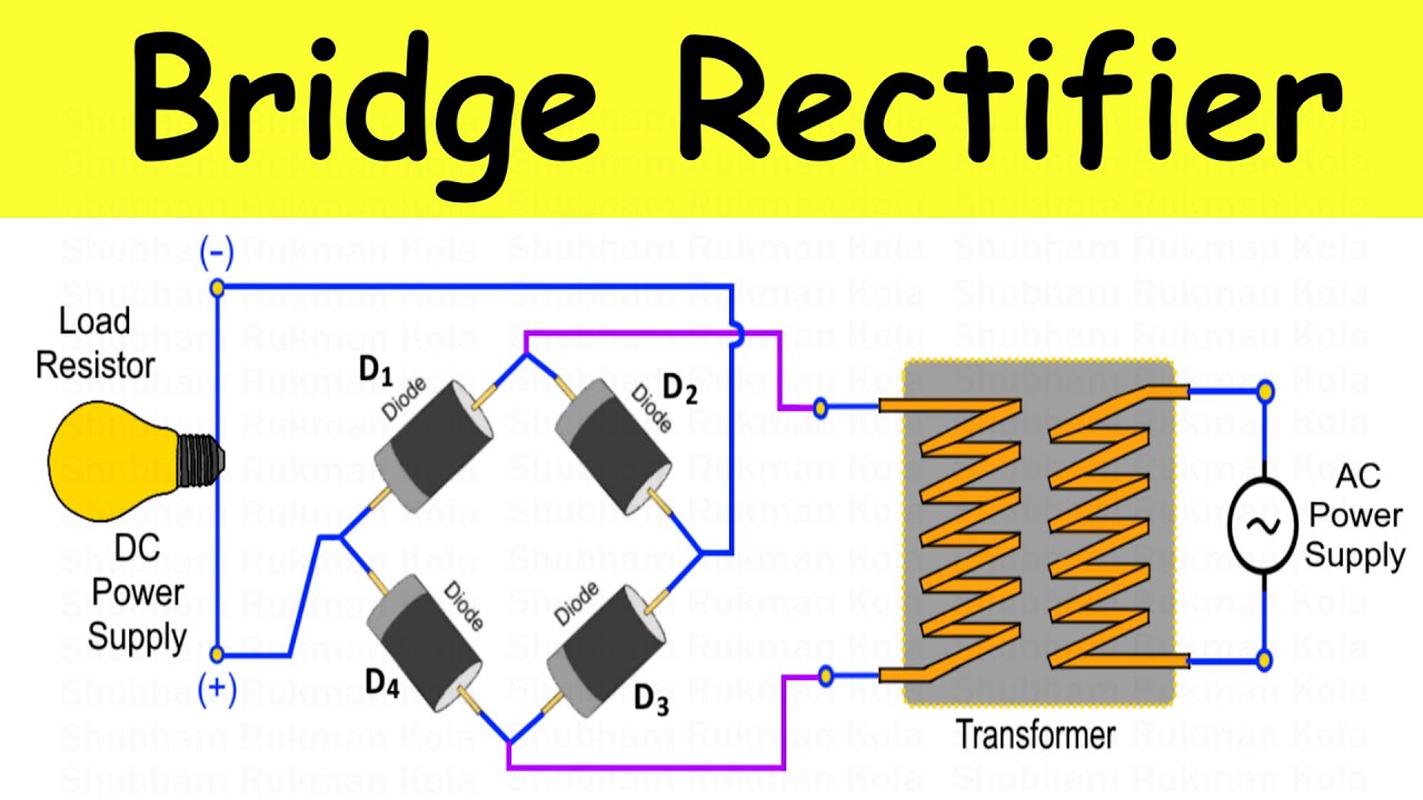
| Efficiency | Low (approx. 40.6%) | High (approx. 81.2%) |
| DC Output | Pulsating and Discontinuous | Pulsating but Continuous |
| Ripple Factor | High (1.21) | Low (0.48) |
| Transformer Utilization | Low | High |
| Cost | Inexpensive | More Expensive |
Market and Industry Trends in Rectification Technology
The field of power conversion is evolving rapidly. While the basic principles of diodes remain the same, the industry is moving toward higher efficiency and smaller footprints.
1. Silicon Carbide (SiC) and Gallium Nitride (GaN)
Traditional silicon diodes are being replaced in high-end power supplies by SiC and GaN semiconductors. These materials allow rectifiers to operate at much higher frequencies and temperatures, which is critical for the fast-charging adapters used in modern electric vehicles (EVs) and smartphones.
2. Active Rectification
In many modern high-efficiency power supplies, “Active Rectification” (or synchronous rectification) is used. Instead of standard diodes, MOSFETs are used as switches. This reduces the voltage drop (which is usually 0.7V for silicon diodes), leading to significantly less heat generation and higher energy savings.
3. Miniaturization
The industry trend is moving toward “Surface Mount Technology” (SMT). Rectifiers that once took up significant space on a circuit board are now smaller than a grain of rice, enabling the slim designs of modern laptops and tablets.
[Image showing market growth chart of GaN and SiC power devices 2024-2030]
Practical Applications of Rectifiers
- Power Supplies: Rectifiers are used in power adapters and chargers to convert AC from the mains supply into DC for electronic devices like mobile phones and laptops.
- Battery Charging Circuits: Used in battery chargers for vehicles, inverters, and emergency backup systems (UPS) to ensure the battery receives the correct DC polarity.
- Radio and Television Circuits: Rectifiers help in providing stable DC power to sensitive radio and TV circuits for proper signal processing and operation.
- Welding Applications: Used in arc welding machines to supply a steady DC voltage for efficient and smooth welding arcs.
- DC Motor Drives: In industrial applications, DC motors require a stable DC power source to control speed and torque, which is provided by large-scale rectifier circuits.
Conclusion: The Future of Power Conversion
Understanding the construction and working of half-wave and full-wave rectifiers is the first step for any aspiring electronics enthusiast or engineer. While the half-wave rectifier is a great educational tool for learning the basics of diode behavior, the full-wave rectifier is the workhorse of the modern world.
As we move toward a more sustainable future, the efficiency of these circuits becomes even more vital. Reducing the energy lost during AC to DC conversion helps reduce the overall carbon footprint of our electronic infrastructure. Whether it is a small charger for your phone or a massive converter for an electric grid, the humble rectifier remains one of the most important inventions in electrical history.
Watch the Full Tutorial: [Insert Video Link Here]
Frequently Asked Questions (FAQs)
A rectifier is an electrical device that converts alternating current (AC) into direct current (DC).
A half-wave rectifier uses only one half-cycle of AC, while a full-wave rectifier uses both halves, making it more efficient.
Because it utilizes both positive and negative cycles of AC, reducing power loss and producing smoother DC output.
Ripple factor measures the amount of AC fluctuations present in the DC output. Lower ripple means smoother output.
Rectifiers are used in power supplies, battery chargers, electronic devices, DC motor drives, and many industrial applications.
![Junction Field Effect Transistor [JFET] Explained: Construction, Working, Application | Shubham Kola](https://shubhamkola.com/wp-content/uploads/2026/04/Junction-Field-Effect-Transistor-JFET-Explained-Construction-Working-Application-Shubham-Kola.jpeg)